Achetez Domestar en direct sur: / Purchase Domestar directly on: / Compre Domestar directamente en: / Acquista Domestar direttamente su: / Domestar direkt kaufen bei:
DOMESTAR Fréquence 1

![]() Deutsch |
Deutsch | ![]() English |
English | ![]() Espanol |
Espanol | ![]() Français |
Français | ![]() Italiano
Italiano
DOMESTAR Fréquence 2

![]() Deutsch |
Deutsch | ![]() English |
English | ![]() Espanol |
Espanol | ![]() Français |
Français | ![]() Italiano
Italiano
DOMESTAR Fréquence 3 (3/8)
![]() Deutsch |
Deutsch | ![]() English |
English | ![]() Espanol |
Espanol | ![]() Français |
Français | ![]() Italiano
Italiano
DOMESTAR Fréquence 3 (5/8)
![]() Deutsch |
Deutsch | ![]() English |
English | ![]() Espanol |
Espanol | ![]() Français |
Français | ![]() Italiano
Italiano
DOMESTAR Fréquence 3 KRUSCHKE (3/8)
![]() Deutsch |
Deutsch | ![]() English |
English | ![]() Espanol |
Espanol | ![]() Français |
Français | ![]() Italiano
Italiano
DOMESTAR Fréquence 3 KRUSCHKE (5/8)
![]() Deutsch |
Deutsch | ![]() English |
English | ![]() Espanol |
Espanol | ![]() Français |
Français | ![]() Italiano
Italiano
DOMESTAR HEXDOME (5/8)
![]() Deutsch |
Deutsch | ![]() English |
English | ![]() Espanol |
Espanol | ![]() Français |
Français | ![]() Italiano
Italiano
Domestar Fréquence 4 (1/2)
Deutsch | English | Espanol | Français | Italiano
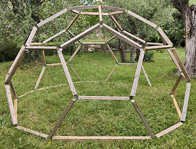
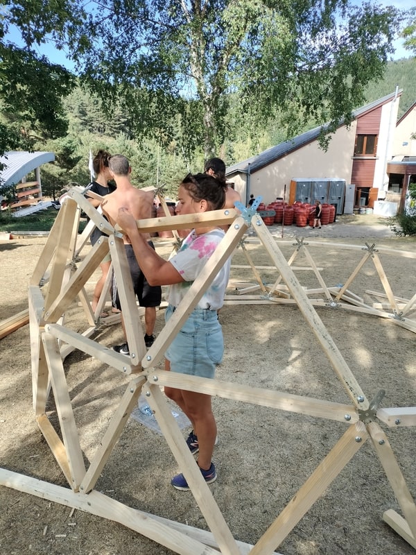
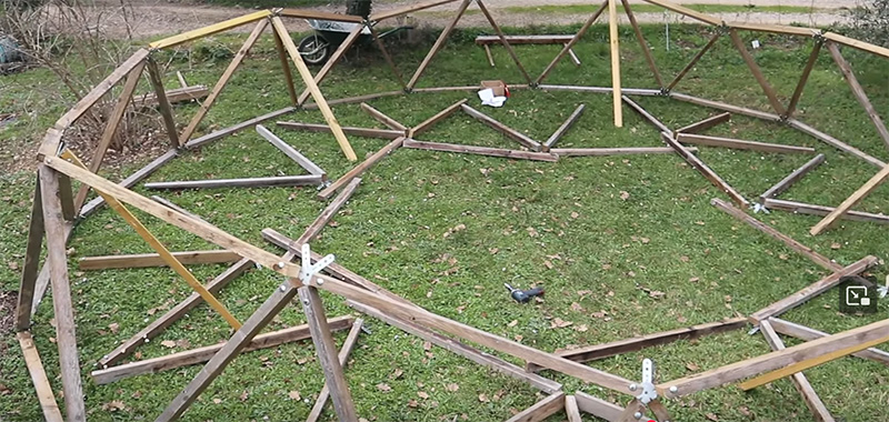
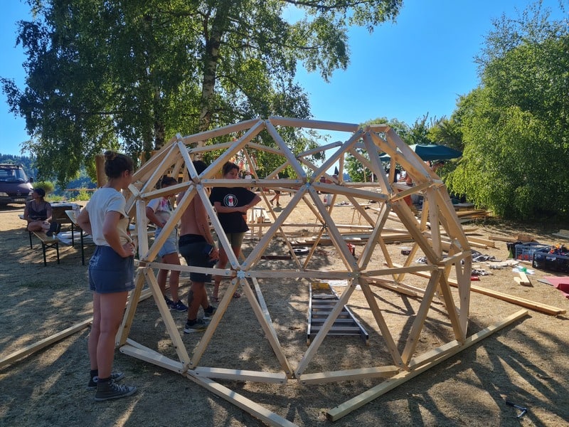
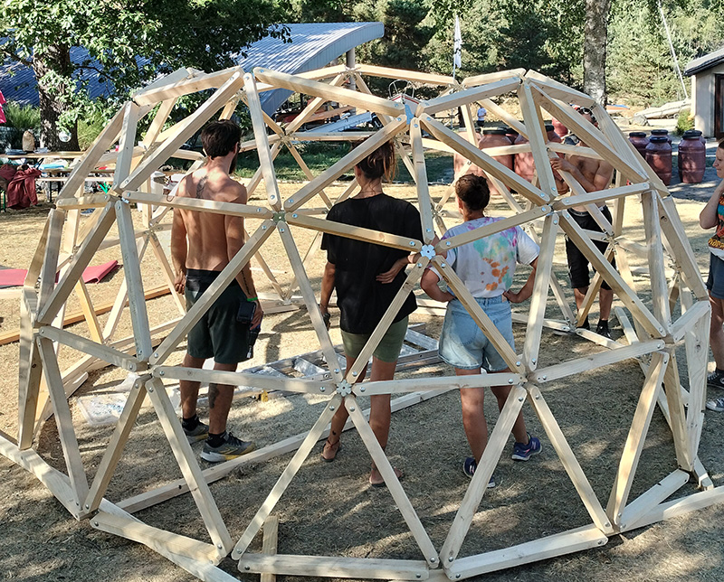
Welcome to the assembly instructions for the geodesic dome using DOMESTAR Frequency 3 5/8 KRUSCHKE connectors. If you have any questions, click on Contact to get in touch with me: I’ll be delighted to help you.
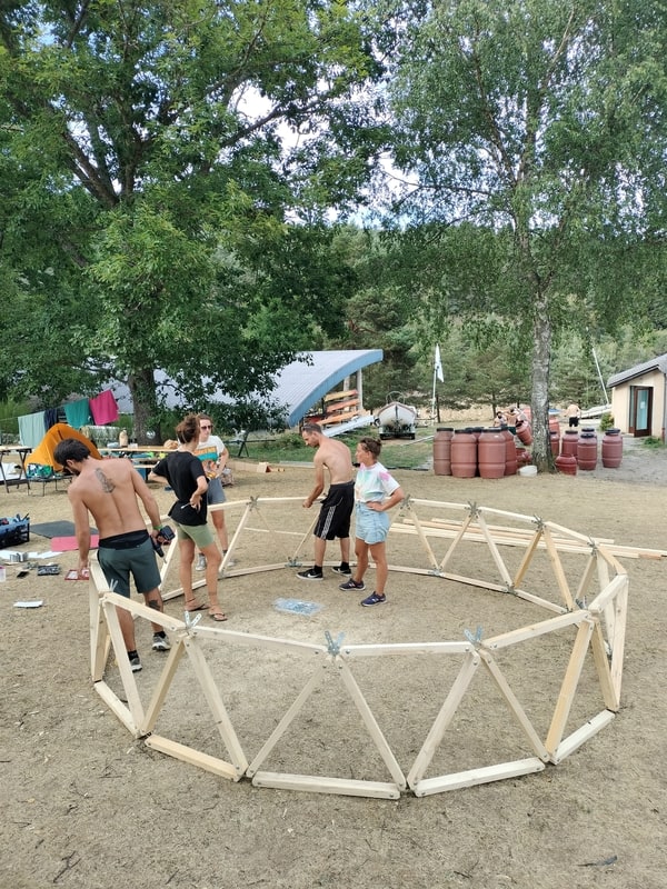
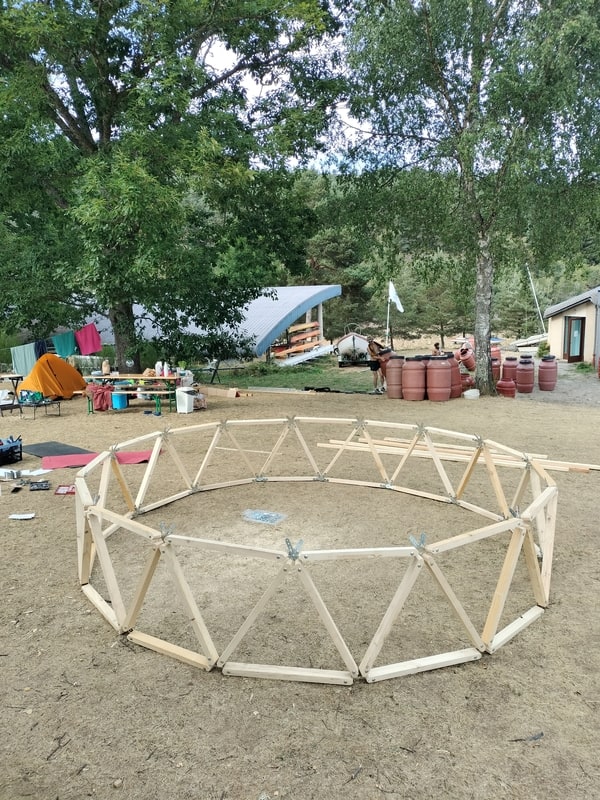
Alix and his team of friends have contributed a large number of the photos in this guide: thanks to the talented team!
Save / Print this page as PDF:

What you need
- Set of 61 KRUSCHKE DOMESTAR Fréquence 3 5/8 connectors
- 165 wooden uprights (joists) in 4 sizes (see size calculation table below)
- 330 bolts: screws and nuts. I strongly recommend TRCC bolts (round head, square neck): one blow from a hammer and they’ll stay stuck in the wood and won’t turn when you tighten them
- For the finish, use between 165 and 330 wood screws, size 5×50 or 5×40
What is “Kruschke”?
Kruschke in “Dome 3V 5/8 Kruschke” means a dome with a flat base. The classic model does not have a flat base, but the Kruschke model does. The 2 models require the same number of connectors and uprights, but the Kruschke model needs 4 different lengths of uprights whereas the classic model only needs 3.
The difficulty of construction is similar. On the other hand, the Kruschke model has 6A connectors and you really mustn’t get the wrong way round (I’ll talk about this later, so be careful!)
Tools required
- something to cut the uprights: ideally a radial saw, otherwise a circular saw or jigsaw
- a drill a drill bit the thickness of the screws
- a spanner or ratchet to tighten the bolts, or an impact screwdriver (note: an impact screwdriver is NOT a percussion drill. With an impact screwdriver, you can screw or bolt much more strongly and quickly) or a simple screwdriver
- a hammer to drive in your TRCC bolts.
- depending on the height of your geodesic dome bench or ladder
Size of your screws and bolts
The bolts must pass completely through the thickest side of the upright and the connector. I therefore advise you to choose a bolt length around 20 mm longer than the thickest part of your wood.
If your bolts are less than 10mm longer, assembly will be much more complicated.
FOR EXAMPLE, if your wood is 40x70mm, you will need to drill through 70mm. So use an 80mm or 90mm bolt.
For thickness, I recommend 8mm bolts (=M8)
I recommend using bolts rather than screws. The assembly is much more solid, as the bolts go through. But above all, dome assembly will be easier.
Choosing the size of your dome
Kruschke’s Domestar 3V (=frequency 3) geodesic dome connectors allow you to mount a “frequency 3” 3/8 geodesic dome with a flat base that uses 4 different sizes/lengths of upright. You will need:
- 20 very large X-poles (colour code Yellow)
- 80 large A-pillars (colour code Blue)
- 35 medium B-pillars (colour coded Green)
- 30 small C-pillars (colour code red)
The size of the uprights will determine the size of the dome. Height, radius and diameter are therefore determined by the length of the uprights.
Explanations:
For a geodesic dome with a radius of 3m (6m diameter) I therefore need to cut:
- 20 very large X-pillars of 1.263m
- 80 A-pillars (large) measuring 1.204m
- 35 B-pillars (medium) measuring 1.087m
- 30 C-pillars (small) measuring 0.929m
NB: If you use another geodesic dome calculator, remember that these calculators often give you the measurements from “hole to hole”, i.e. the centre of the connector. However, there is 3 cm between the centre of the connector and the start of the branch of the connectors (this is the centre circle of my connectors). That’s why the 2 “hole to hole” columns are 6cm longer.
Optimising your wood cuts and purchases
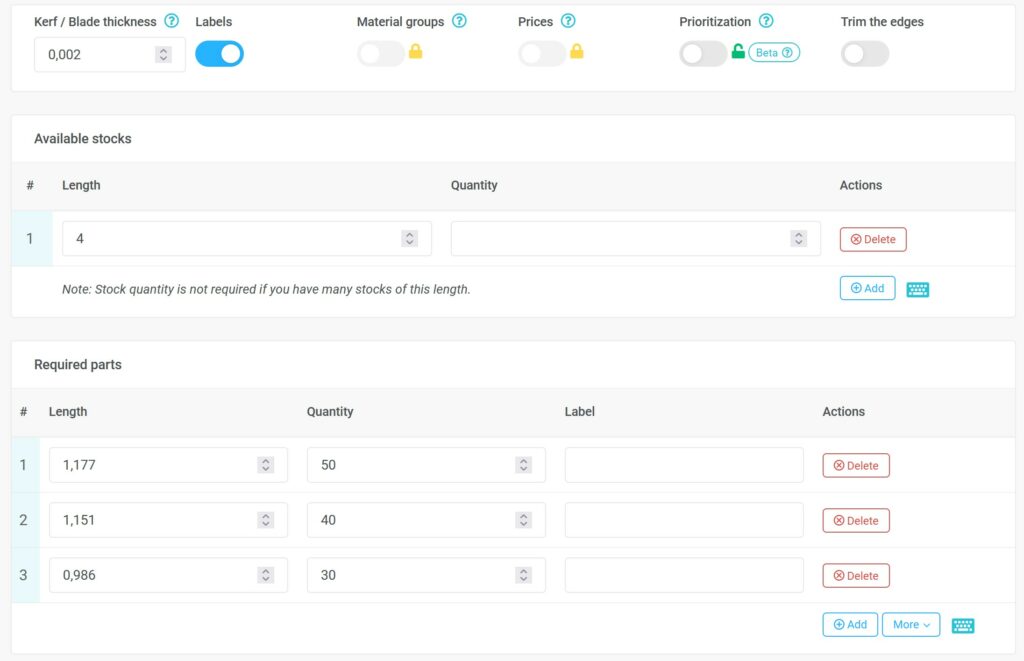
I recommend this free internet application to help you optimise your choice of wood to buy and cut: Optimcutter
Here are the parameters, for example, for a 6m diameter dome (3V 3/8 NON Kruschke), a 2mm board and 4m joists:
What does 3/8 or 5/8 mean in 3 5/8 frequency?
Frequency 3 geodesic domes come in 2 formats: 3/8 and 5/8 (sometimes also called 4/9 and 5/9 or even 5/12 and 7/12: it’s just a habit! The domes 3/8, 4/9 and 5/12 are all exactly the same).
This is the division of the sphere:
- 3/8: a little less than half the sphere
- 5/8: a little more than half the sphere. These domes are one level higher than the 3/8 domes: they are therefore taller.
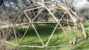
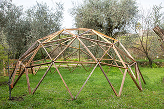
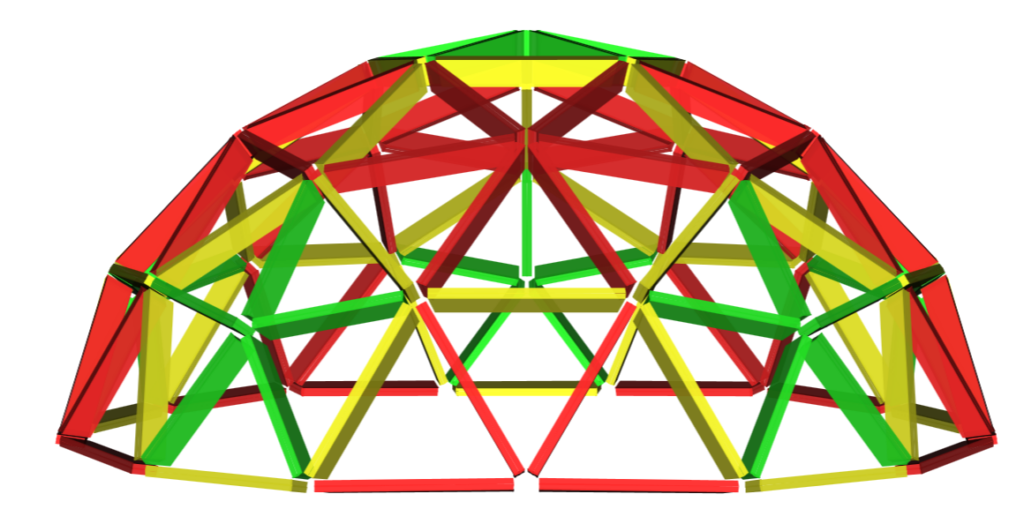
Here is an example of a 3V 3/8 dome:
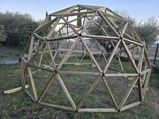
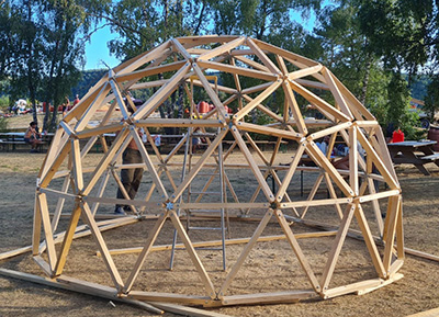
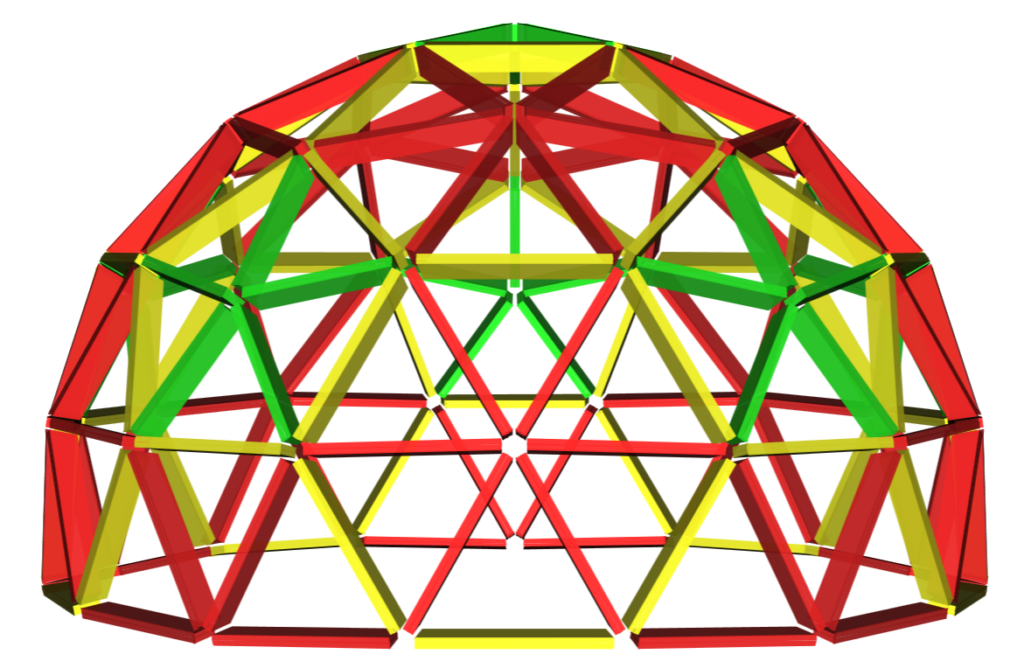
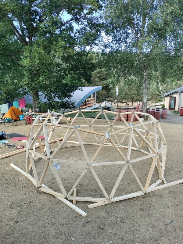
And the 3V 5/8 dome:
Which wood should be used for geodesic dome uprights?
I recommend using construction or decking timber that offers good strength at a fair price.
The MINIMUM length and width of the uprights should be 30mm to ensure the stability of the structure.
Decking joists are very attractive, with dimensions of around 62x38mm or 70x45mm. The joists are also often treated to class 3 or class 4, giving this wood very good resistance to rain.
Construction rafters / half-rafters (on the websites of major building retailers, type in “construction timber”) are often even cheaper and thicker with dimensions of 75×50, but their treatment and rain resistance is often inferior (generally class 2 – this is yellow-coloured wood)
TIP: choose your own wood from the big building stores. Check that the wood is not twisted or warped. Twisted joists will make assembling your geodesic dome much more difficult!
TIP: If you plan to treat the wood, I advise you to do so after cutting the wood but before assembling it: it will be easier to paint/spray the wood flat than once the geodesic dome has been assembled.
TIP: buy a few extra large uprights: they will be needed to support the high levels of the dome during construction.
ATTENTION: if you choose uprights with widths greater than 38mm you may need to bevel some of the uprights: do a test on a 6-point connector with your uprights to see if the ends are not touching. If they do, then bevel them a little.
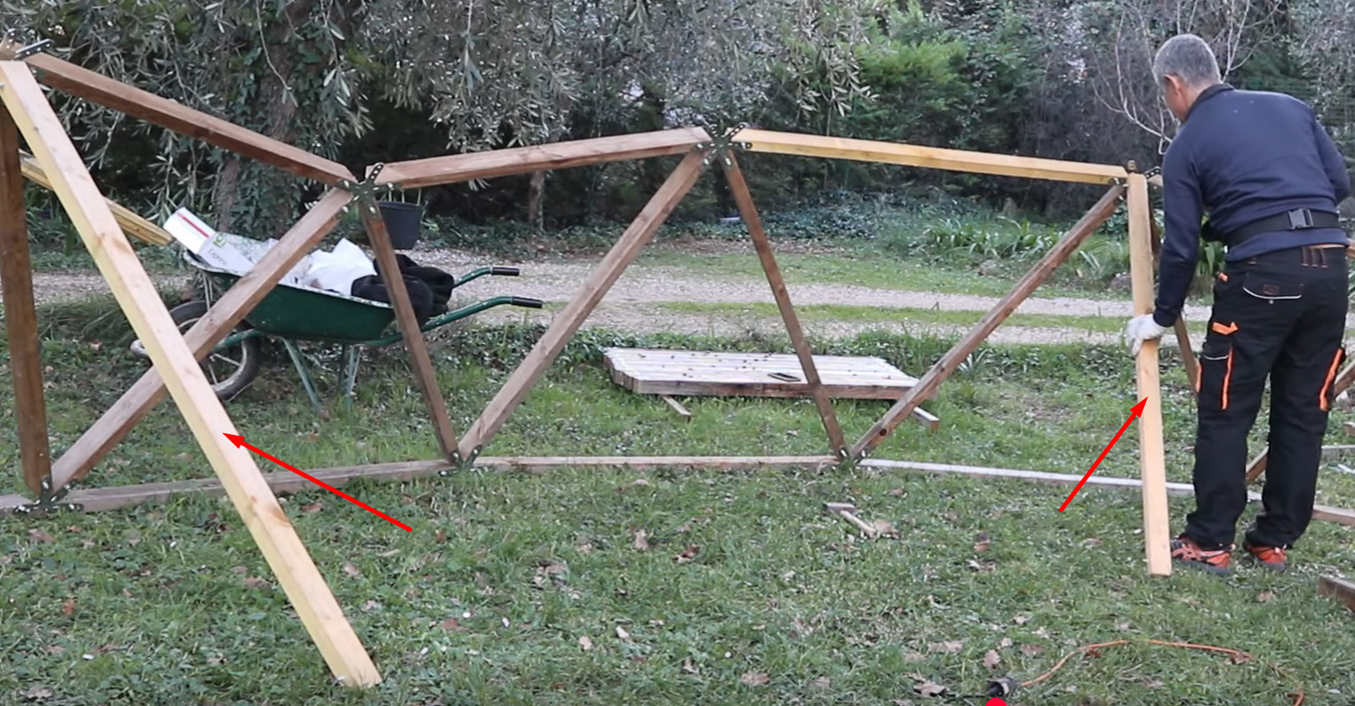
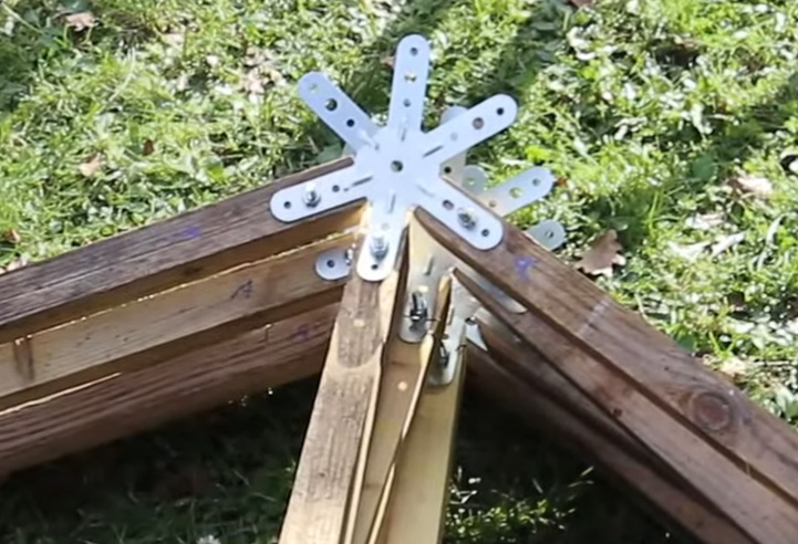
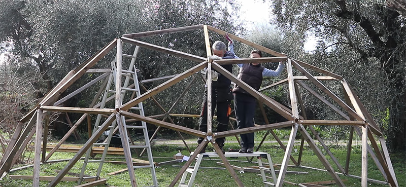
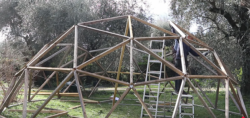
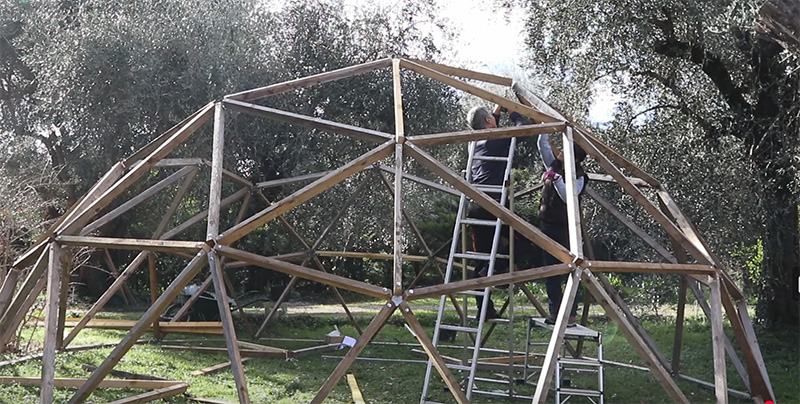
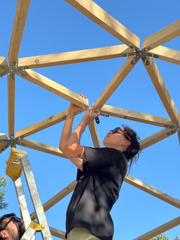
My experience of fitting the domestar V3
A frequency 3 dome is more difficult to assemble than my domestar V1 and domestar V2: there are a lot more parts to assemble and more uprights are levered and therefore require supports during assembly. Here are my recommendations:
- Leave the triangles that don’t yet have a support for as short a time as possible without a support: as soon as you’ve assembled 2 triangles, connect them with the belt and continue to add the belt when you add triangles
- 1st floor: absolutely provide a support until the belt is fitted
- 2nd floor and above to be done by 2 people. Provide supports
- From the 2nd floor onwards, the connectors start to bend under the strain of assembly. But don’t worry: once everything is assembled, the connectors will return to “normal”
- Mark the letters on the uprights CAREFULLY (X; A; B and C): it’s very easy to get the wrong upright. Take the time to check regularly.
- At the end of construction, add wood screws to the small holes in the Domestar connectors. The minimum is 3 screws/connector, but ideally you should fill all the holes to ensure maximum stability. Don’t screw in the wood screws until the dome is completely finished, to give the dome time to correct itself during assembly.
- On some of Alix’s photos you can see that he has written the letters A, B, C at the end of the upright: I advise against doing this as the connectors will cover the letters and it will be impossible to check that you haven’t made a mistake. Putting the letters about 10 cm from the end makes it easier to check. Personally, I use erasable Stabilo “woodys”.
Preparing to build the geodesic dome
During this preparation phase we will:
- Cut out the uprights
- Drill all the uprights
- Insert all the screws
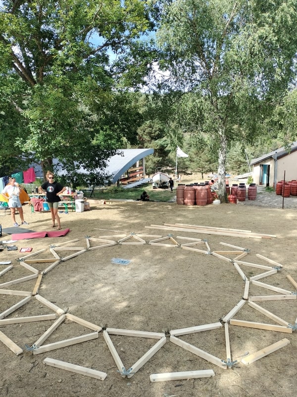
Prepare the location for the geodesic dome
Once you have determined the diameter of the geodesic dome using the table above, make sure that you have enough space for your dome and that this space is flat enough.
Cut out the uprights
You are going to cut:
- 20 very large X uprights (colour code Yellow)
- 80 large A uprights (colour coded Blue)
- 35 medium B-pillars (colour code green)
- 30 small C-pillars (colour code red)
Start by cutting out the first upright and checking that its length is exactly what you wanted.
Use this first upright as a template: trace the cutting line on the wood to be cut using this upright. Remember to cut just after the cutting line, not on top of it, to allow for the thickness of the blade.
Bevel some joists if necessary
Depending on the thickness of your joists, it may be necessary to bevel some of them before assembly to prevent them from touching each other on the connector.
More information on bevelling and joist bracing.
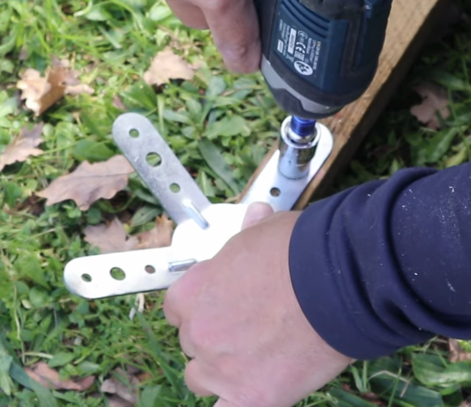
Drilling the studs
Now it’s time to drill the studs to accommodate the bolts. Here again, great precision will help you with the installation.
The bolt hole should be 40mm from the end of the upright.
You need to drill through the LONG side of the upright to ensure maximum stability for the dome.
Create a drilling pattern for greater precision
I strongly recommend that you create a drilling template.

Make your first hole very precisely on one side of the first stud.
Mark the side from which your drill bit entered: as you risk not drilling straight through, only the side where you started drilling is accurate. The exit side is likely to be off. This isn’t serious, but to be accurate you need to base yourself on the entry side.
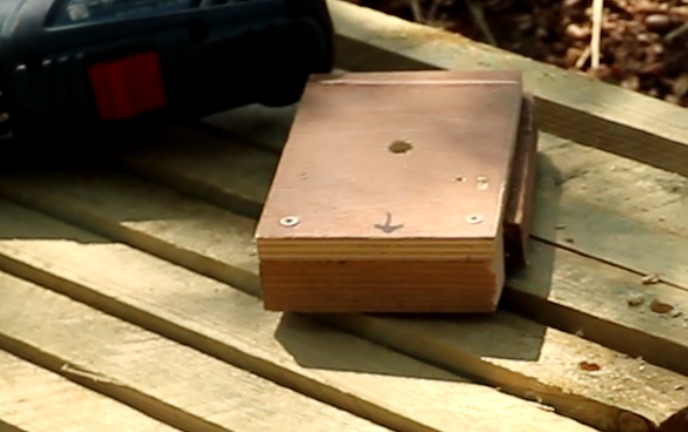
Now turn the upright over and place a small piece of wood underneath. Screw shims tightly against the jamb around this wooden plate.
Finally, drill the wooden plate through the jamb, entering the drill bit through the EXIT hole.

That’s it, your pattern is ready.
Now finish the holes in the uprights, using your template and trying to drill as straight as possible.
Mark the side where you put the drill bit in: this is the side that will be placed against the connectors, as it is the most accurate side.
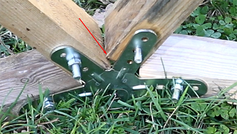
Insert the bolts into the holes. Pay close attention to the direction of insertion: insert the bolts through the OUTPUT of your drill bit. This way, the end of the bolt is on the same side as the entrance to your drill bit and this is the side that will be against the connector.
Use the hammer to ensure that the square part of the TRCC bolts penetrates the wood.
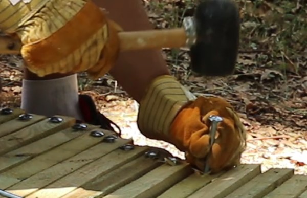
Tip: if the hammer isn’t enough, you can use a screw and washer and tighten the bolt so that it goes into the wood.
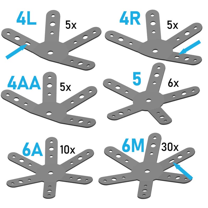
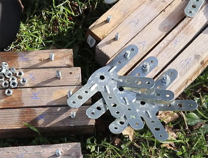
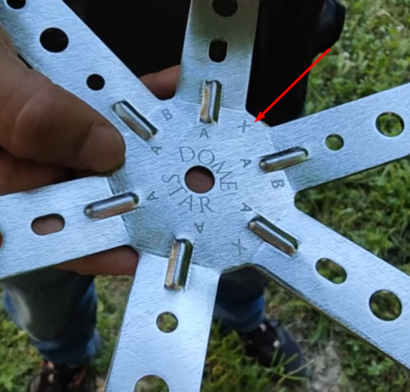
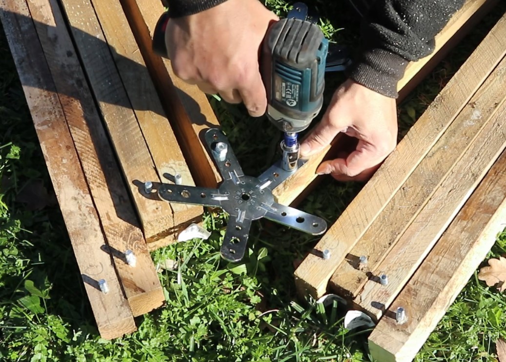
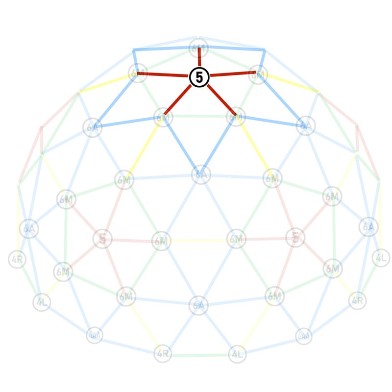
Presentation of connectors
In your Domestar pack you’ll find 4, 5 and 6-leg connectors.
I advise you to start by sorting your connectors:
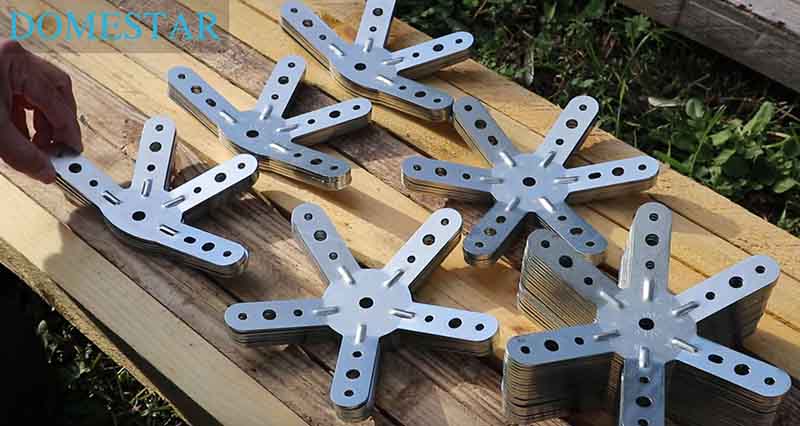
WARNING: there are:
- 3 different types of 4-leg connectors
- 2 different types of 6-leg connectors
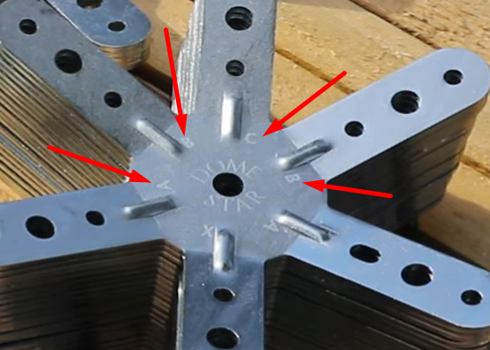
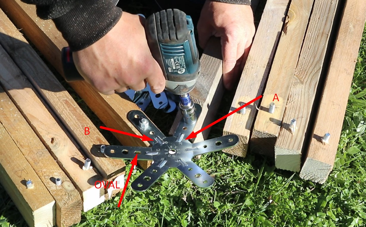
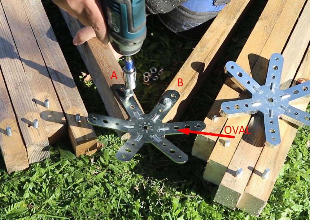
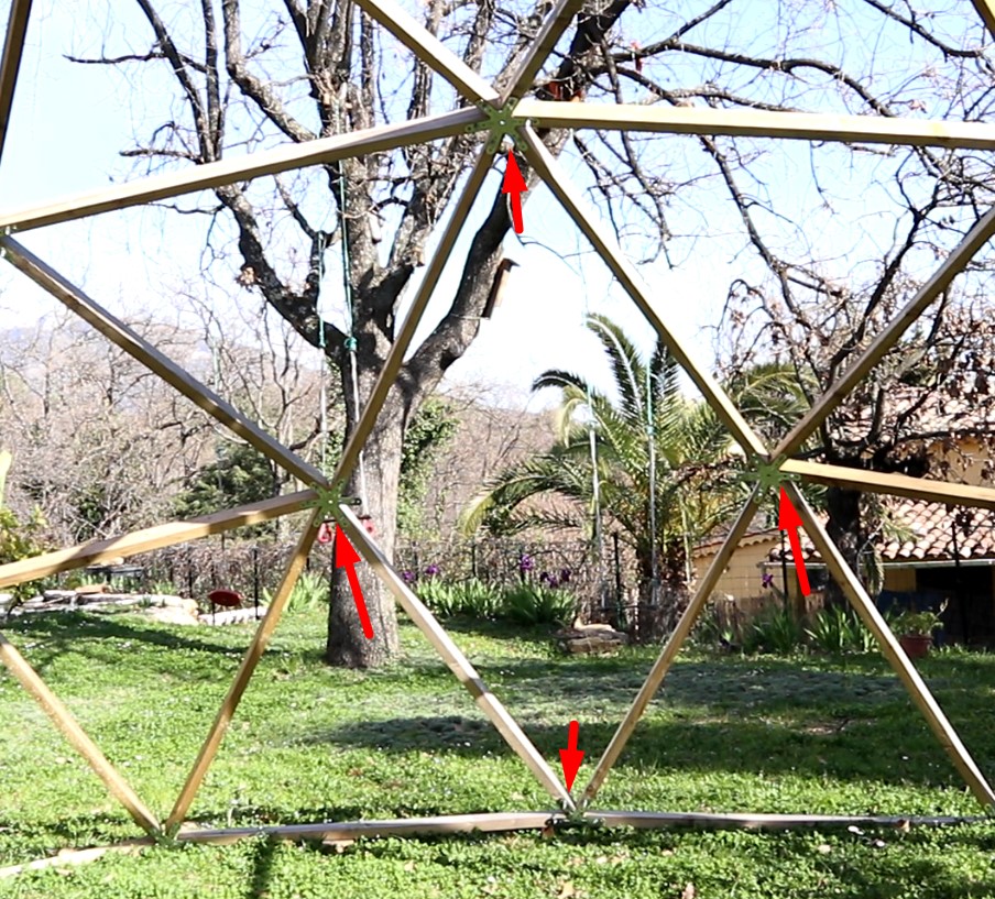
The drawing above shows the distinguishing marks that allow you to tell the difference between the connectors.
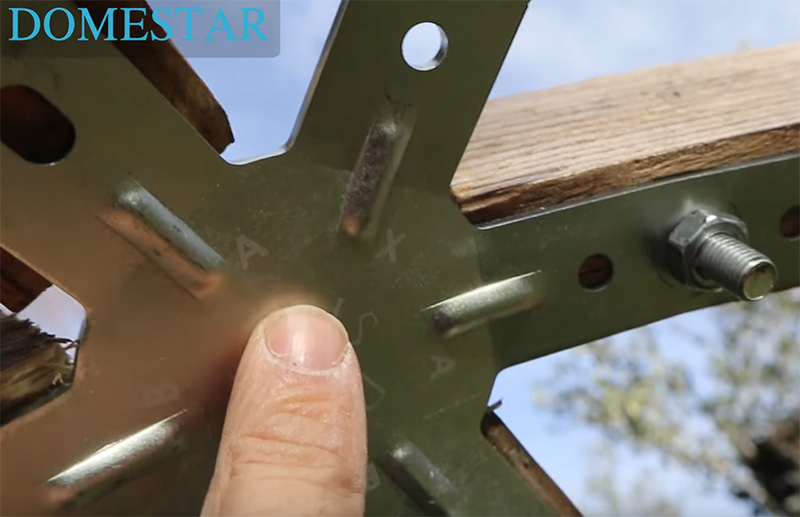
Each leg also has a letter engraved on it so you know whether you need to fit an X, A, B or C stud:
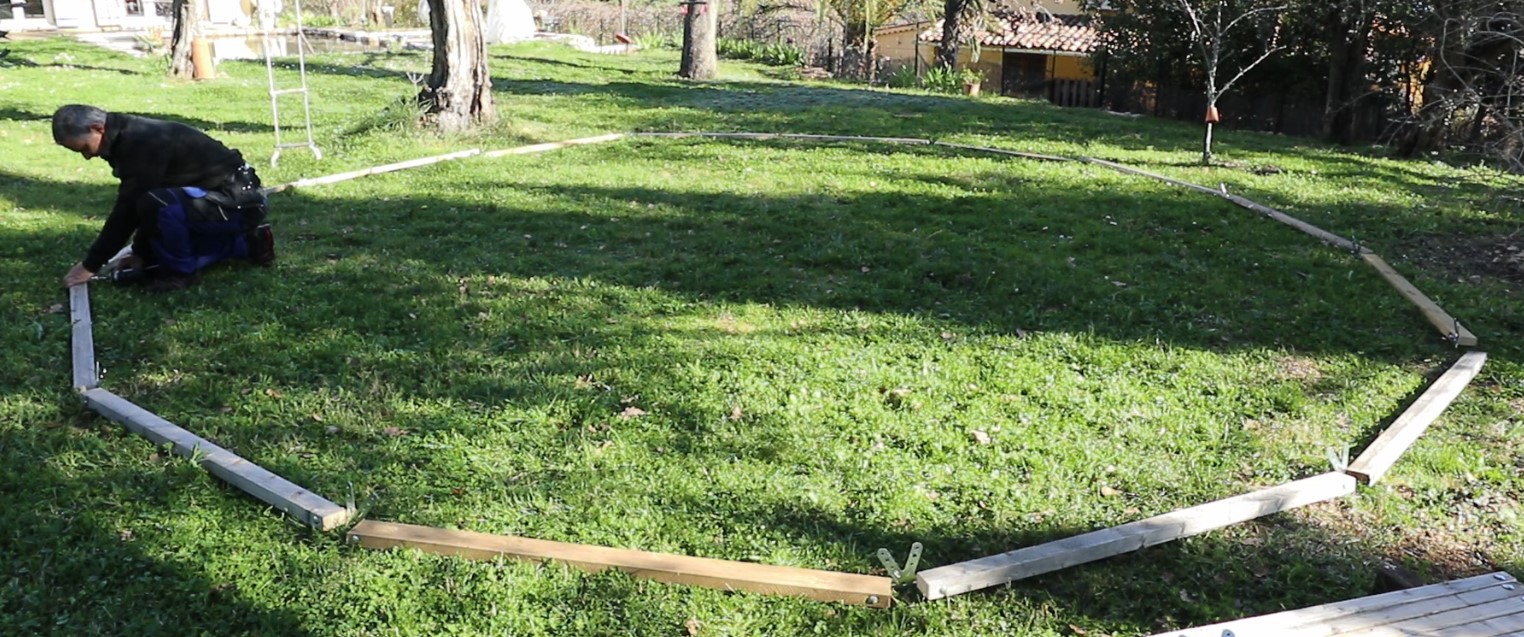
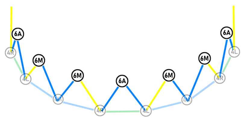
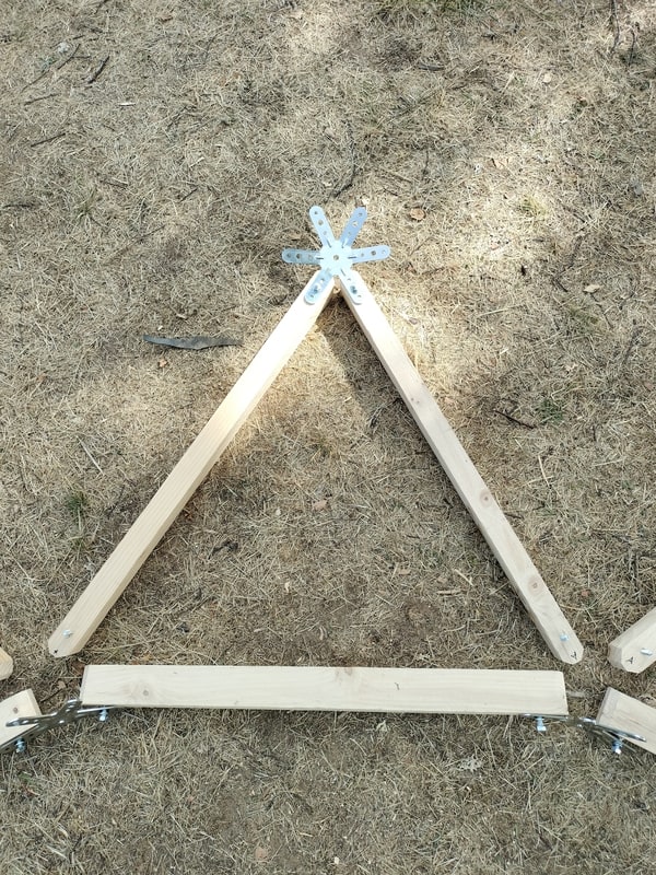
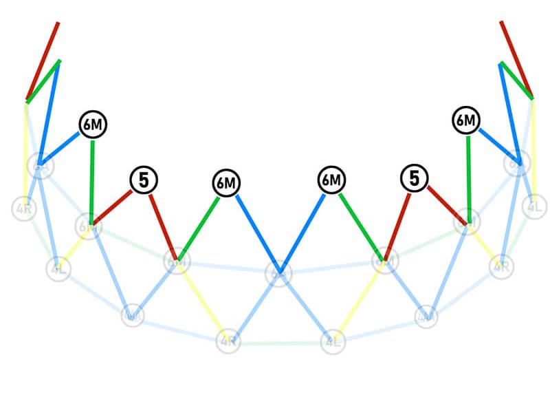
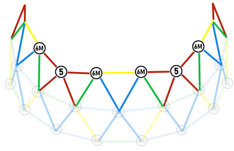
Step 1: the base
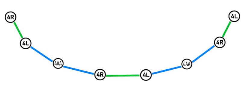
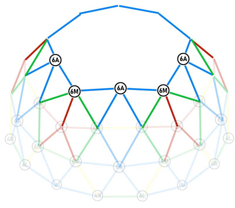
The colour of the lines indicates which amount to use:
- blue: large amount A
- green: medium amount B
- red: small amount C (not used at this stage)
- yellow: very large amount X (not used at this stage)
Parts required:
- All 15 4-pin connectors
- 10 A-pillars / blue / large
- 5 green / medium B-pillars
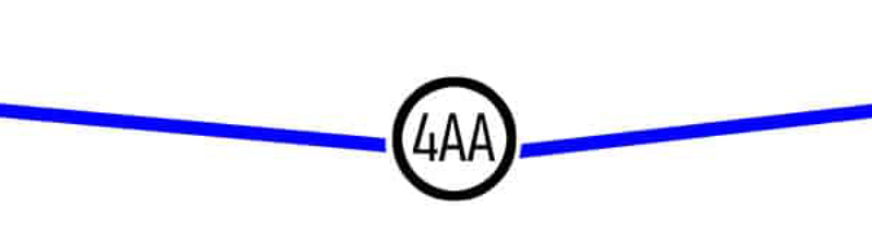
Assemble 5x A-posts / blue / large on either side of the 4AA connectors
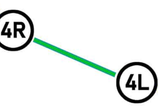
Assemble the 4R and 4L 5x on either side of the B / green / medium uprights.
Finally, assemble and screw the base to the floor, alternating our two types of uprights.
Step 2: First level
Parts required:
- 5 6A connectors (CAUTION: these connectors have a direction!)
- 10 6M connectors
- 20 A-pillars / large / blue
- 10 X-pillars / very large / yellow
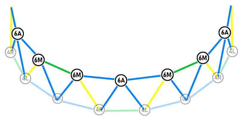
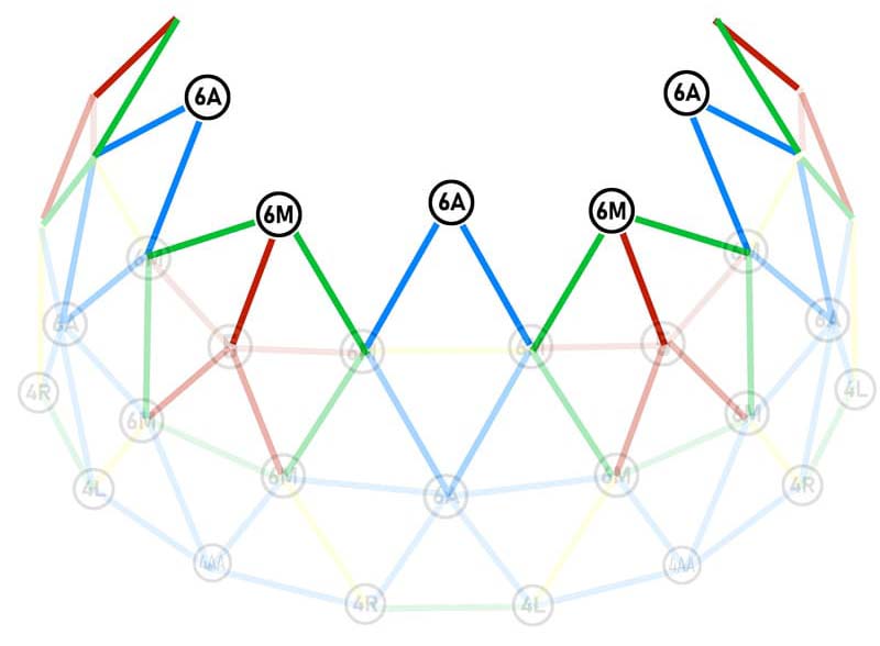
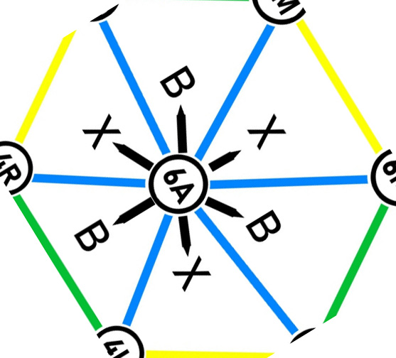
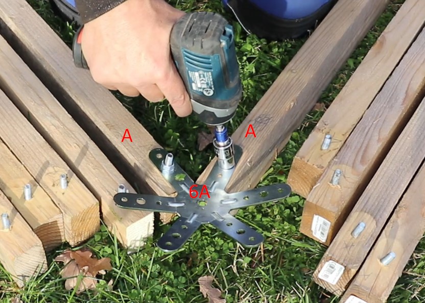
I’m going to start with the 5 6A connectors because it’s easy to make a mistake here. Look closely at these connectors: they have 6 A legs, but between the legs there are intermediate letters.
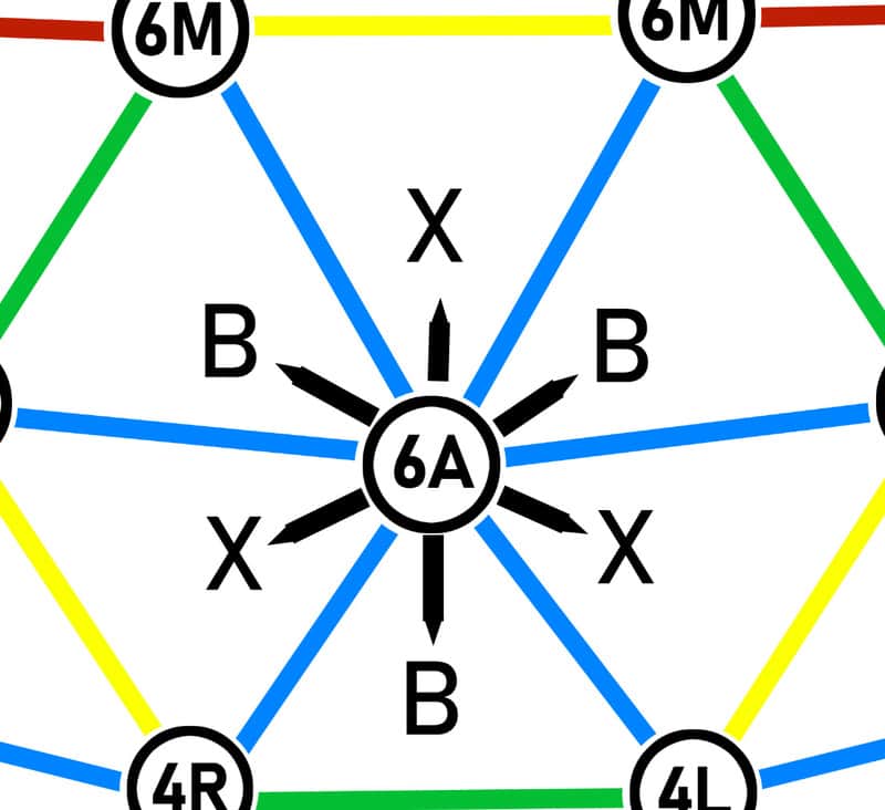
These intermediate letters indicate which upright the 6A connector should face.
Looking at the diagram in step 1, I see that the 6A must be oriented with the letter B pointing downwards: the letter B points towards the green upright = B = medium. So when I screw my 6A connectors to the 2 A-pillars, I have to choose the 2 legs that have a B on either side.
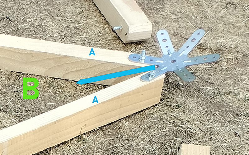
So on each of the 5 6A connectors, assemble 2 A-pillars (large/blue) on either side of the letter B.
Using the first 5 6M connectors, assemble an A-pillar on the right and an X-pillar on the left:
For the last 5 6M connectors in this step, do the opposite: an A-pillar on the left and an X-pillar on the right.
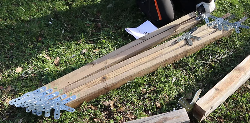
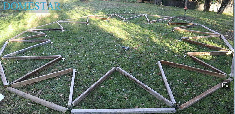
Preparing the triangles on the base
I’m going to prepare everything on the ground before I start assembling the first level, so assembly will go very quickly and I’ll leave the triangles unsupported for as little time as possible.
Place the 5 triangles 6A opposite the B / Green / Medium uprights and the 6M in the free slots, taking care to match the letters on the uprights with the connectors on the base.
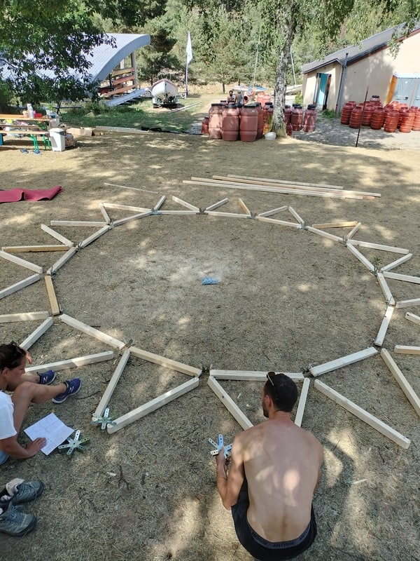
Take your time to check that everything is good!
Preparing the first floor belt
Still with a view to leaving the triangles unsupported for as short a time as possible, we’re going to prepare the first belt on the floor. To do this I’ll need:
- 10 A-pillars / large / blue
- 5 B-pillars / medium / green
Place the A / large / blue uprights on either side of the 6A connectors and the B / medium / green uprights between 2 6M connectors.
Make a final check that the letters match before assembling the first level.
Screwing on the first level and the first belt
Start with any triangle and turn around the base. As soon as you have made the first 2 triangles, immediately attach the belt post. Keep going by screwing on 1 triangle, then immediately the belt upright above it.
I’d also advise you to support the belt with temporary uprights until you’ve finished the whole belt.
Second level
Materials required:
- 10x A (Large / Blue),
- 10x B (Medium / Green)
- 10x C (Small / Red)
- 5x 5-pin connectors
- 10x 6M Connectors
Assembling the 5 CC triangles
Take 10 small C-pillars and 5 5-pin connectors. Screw these connectors to 2 uprights.
Assembling the 10 6M triangles
Be careful, it’s quite easy to make a mistake if you’re not careful.
For the first 5 triangles, you need to put the B uprights on your right and the A uprights on your left.
For the next 5 6M triangles, it’s the opposite of the previous step: you now have the A-pillars on your right and the B-pillars and oval on your left.
Assemble 5 triangles.
Prepare the triangles on the floor
I’m not going to start assembling straight away: I’m going to prepare everything on the floor. Carefully following the “second level” diagram, lay the triangles on the floor:
- the CC triangles with the 5-pin connector opposite the green/medium uprights (between 2 6A)
- the 6M triangles in the remaining spaces, taking great care to match the letters on the uprights with the letters on the branches on the dome.
Prepare the second belt
As with the first level, I’m going to prepare the second belt on the floor so that the triangles are left unsupported for as little time as possible.
I’ll need:
- 10 C-pillars / red / small
- 5 X uprights / yellow / very large
Place these uprights on the floor next to the triangles on the floor, following the diagram above.
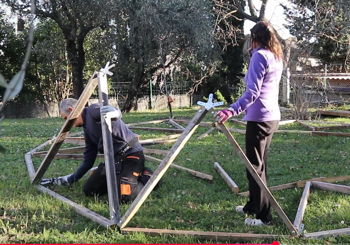
Assembling the second level and its belt
ATTENTION: 2 people are strongly recommended for these steps. I also recommend using supports for these triangles until the second belt is installed. This is where things get complicated, so start this stage in good shape 
Assembling the second level is exactly like the first level in principle:
- Start by screwing on the first triangle and supporting it with a temporary upright
- Screw on the triangle immediately next to the first triangle
Third level
I’m going to need:
- 5 connectors 6A
- 5 6M connectors
- 10 A-pillars / Blue / Large
- 10 B-pillars / Green / Medium
- 5 C-pillars / Red / Small
Let’s start by assembling 5 triangles, each with 2 A-pillars and a 6A connector.
WARNING: VERY VERY IMPORTANT! The 6A connectors have a meaning, even if they have 6 identical A legs. Don’t get it wrong!
In addition to the letters A on the connector legs, 6A connectors also have intermediate letters. Make sure you orientate these letters towards the right uprights. Here, we have the X / yellow / very large uprights towards the bottom of the connector when looking at the assembly drawing. The letter X on the connector should therefore be pointing downwards!
6M triangles
Screw the B-pillars (2 B-pillars/connector) and C-pillars (1 C-pillar/connector) onto each of the 5 6M connectors:
Prepare the floor triangles
I place each 6M connector opposite the 5-pin connector, with the C-pillar connecting to the 5-pin connector.
The 6A triangles are placed in the remaining space, facing the very large X-pillars.
Prepare the third belt on the floor
I need..:
- 10 A-pillars / large / blue
I place them on the floor between each triangle already on the floor.
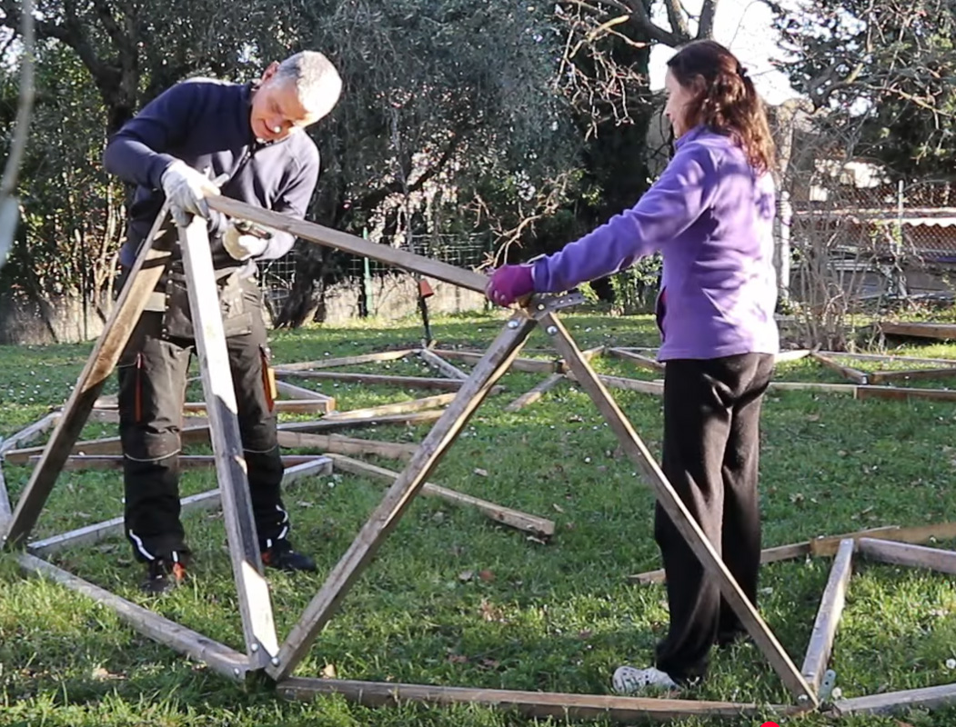
Assembling the third level
Here again I advise working in pairs
Assembling the second level is exactly the same as for the first and second levels in terms of principles: first you screw on one triangle, then its neighbour, then the belt post that connects the 2 triangles. Then you continue with the neighbouring triangle until you’ve gone all the way round.
Support the belt regularly.
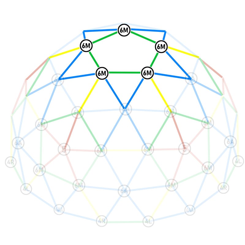
Fourth level
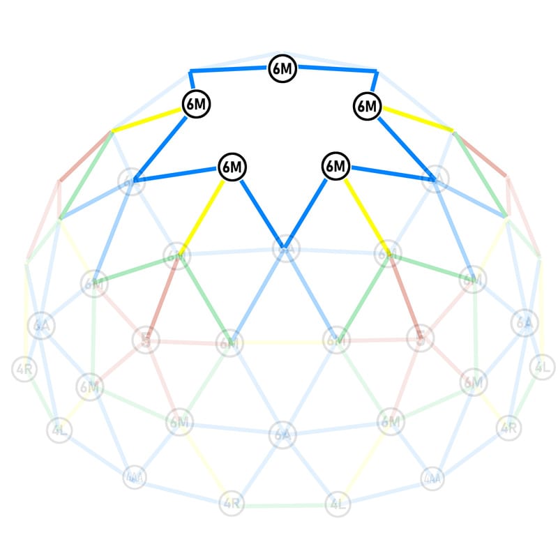
Materials required:
- 10x A (large)
- 5x X (very large)
- 5x 6M connectors
Now you know what to do just by looking at the diagram above! On each of the 6M connectors, screw 2 A-pillars and an X-pillar between the A-pillars: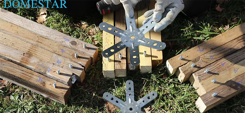
Prepare the 6M triangles on the ground
The very large X-pillar that you screwed into the centre of the 6M triangles will screw into the 6M connectors on the dome: they are easy to recognise, they are the only ones on the dome that have a single free leg (you also marked X on the free leg of the connector!)
Place them on the ground waiting for the belt.
Prepare the fourth belt on the ground
Equipment required:
- 5 B uprights / green / medium
Place the uprights on the floor between the triangles that have already been laid.
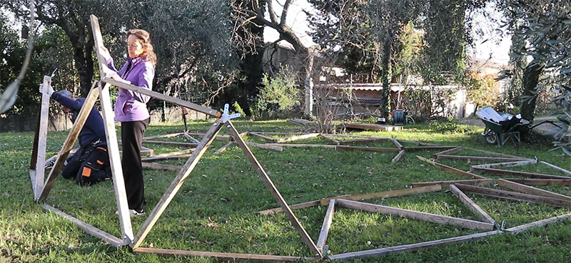
Assembling the fourth level and its belt
As usual, we start by screwing 2 neighbouring triangles together:
and screw the belt between these 2 triangles:
… and I continue to go round.
Last pentagon
I’m almost at the end!
All I need for this final stage is:
- 1 5-pin connector
- 5 C-pillars / small / red
I screw the 5-pin connector onto a C-pillar
I screw this upright onto the dome. It needs to be supported while the other connectors are installed.
I install the 4 missing connectors by screwing them on.
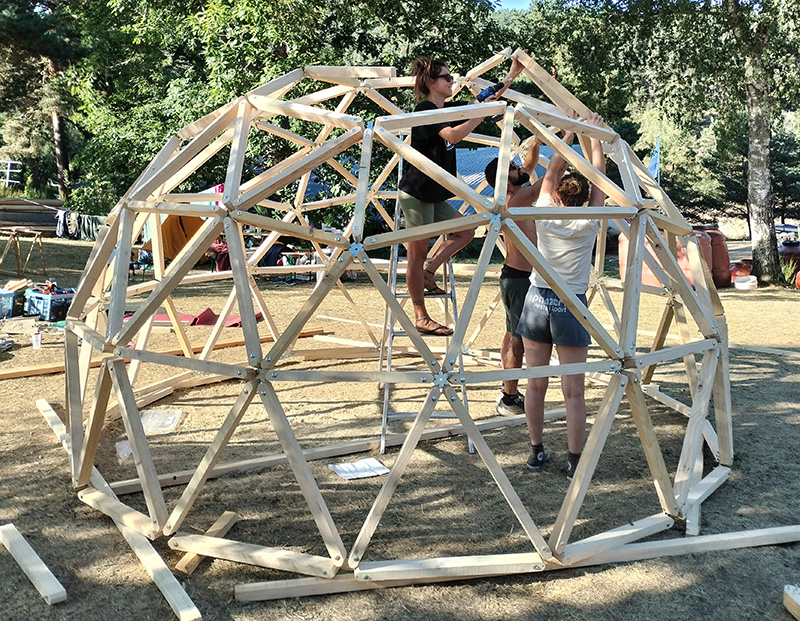
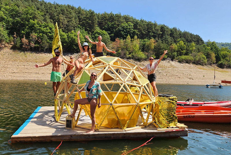
Your dome is finished!

The great adventures are yours!
Finishes
Wood screws to prevent slipping
Your bolts are held in place by compression and over time they can unscrew and the connectors will start to turn. To prevent this undesirable rotation, I advise you to add at least 3 wood screws per connector, as follows:
For maximum stability, fill all the small holes in the domestar connectors with wood screws.
Where can I buy the necessary materials?
If you have any advice to share about buying materials, please write to me and I’ll post the best tips here!
Wood
When it comes to wood in France, you can find decent prices without having to negotiate in the big building stores: Castorama, Leroy Merlin, Brico Depot… I find that the professionals are sometimes much more expensive than the building superstores unless you have an account and negotiate for a long time.
Bolts
For bolts I found the best prices in Europe at auprotec(website) with fast delivery and reasonable prices.
TIP: it is often worth buying 100 bolts rather than 50 because of their policy of reduced prices according to quantity.
Direct link to TRCC bolts
How do I fit a door into a geodesic dome?
I don’t have any experience of dome doors, but I’m sharing on this page my ideas on how I would go about inserting a door into my domes.
However, it’s easy to remove 1 upright from the first belt to leave an easy passage:
In these cases, I advise you to reinforce the structure by adding wood screws in each free hole of the 4 connectors around your new opening.
Remove this amount at the end of construction: not during construction.